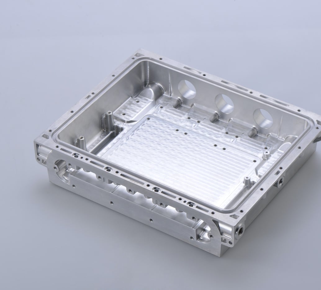
Flat, pocketed or bracket-like components are usually milling candidates.
PRECISION MILLING SUPPORT
CNC Milling for Flats, Pockets, Holes and Precision Milled Features
FREEFLY CNC uses CNC milling for flat faces, pockets, slots, hole patterns and prismatic features, while keeping Swiss turning and CNC turning as the core route for rotational components.
Milling performance depends on geometry, workholding, tool access, material, tolerance and quantity. FREEFLY CNC uses milling where flat, pocketed or multi-face features need a controlled route.
orthographic geometry / tool access
~±0.01 mmTypical tolerance on suitable features
~7 DaysTypical sample route, project-dependent
500+ pcsProduction strength, samples supported
ISO 9001Quality management system
/ Process Fit
When milling is the right route
Milling is appropriate when the part needs prismatic geometry, machined faces or multi-face features that cannot be produced efficiently by turning alone.
Pocket depth, corner radius and wall thickness affect machining stability.
Position to datums, thread depth and counterbore relationships must be clear.
Shafts or sleeves may still start with turning, then receive milled features.
/ Capability Fit
Process fit matters more than machine labels
A buyer needs to know whether the feature can be held, reached, inspected and repeated.
Each setup adds handling, alignment and inspection work.
Deep, narrow or hidden features change tool length and stability.
Clamping must protect functional and visible surfaces.
Features should be measurable against the drawing requirement.
/ Feature Library
What CNC milling adds to precision components
The feature library turns broad service language into terms engineers can map to drawings.
Milling checkpoint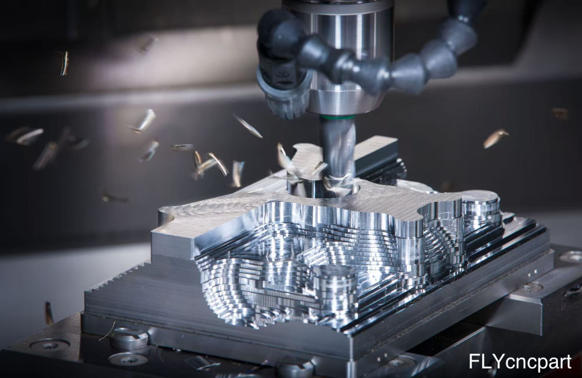
01 / FOCUSPlanar faces
Check tool access, setup direction, surface requirement and tolerance stack before production.
/ Internal Radii
Tool geometry shapes the part
Rotary cutters create internal radii. Smaller radii usually require smaller tools and more conservative cutting.
Increase radius where function allows to improve tool stability.
Tool size affects cycle time, finish and depth capability.
Deep pockets can increase chatter and deflection risk.
The part must allow stable tool entry and exit.
/ Walls and Pockets
Thin features need early review
A tolerance that looks simple on a rigid block can be difficult on a thin wall or deep pocket.
Milling checkpoint01 / FOCUSWall deflection
Check wall thickness, depth, access and material behavior before machining.
/ Holes and Threads
Hole details affect fit and assembly
Drilling and tapping become risky when usable depth, exit condition or gauge expectation is unclear.
Bottom geometry and chip evacuation affect process choice.
Specify usable depth, pitch and functional requirement.
Fastener seating and datum relationships should be defined.
Define deburr and edge condition before parts reach assembly.
/ Setup Strategy
Every reorientation has a consequence
Opposite-side features and multi-face geometry can require additional setup and datum transfer planning.
Milling checkpoint01 / FOCUSFunctional datums
Confirm which feature locates the operation so machining and inspection use the same reference.
/ Materials
Material changes milling behavior
Material affects heat, tool wear, burr formation, clamping force and final surface condition.
Strength and hardness condition influence tool life and edge control.
Grade and chip behavior require careful review.
Often production-friendly, while thread, plating and documentation still matter.
Good machinability, with thin-wall and anodizing effects to consider.
/ Quality CTQs
Inspect the features that drive assembly
Quality planning should connect to drawing features, not only to a general quality statement.
| Requirement | Manufacturing Focus | Buyer Value |
|---|---|---|
| Datum faces | Flatness and orientation matter when faces locate the assembly. | Keeps milling, inspection and final part requirements aligned. |
| Hole position | Check position relative to functional datums. | Keeps milling, inspection and final part requirements aligned. |
| Pocket depth | Depth controls clearance, seating or volume depending on function. | Keeps milling, inspection and final part requirements aligned. |
| Thread function | Use thread gauge or fit requirement where specified. | Keeps milling, inspection and final part requirements aligned. |
/ Cost Drivers
What changes milling cost
Cost is shaped by setup count, tool reach, tolerance scope, material behavior and inspection needs.
| Requirement | Manufacturing Focus | Buyer Value |
|---|---|---|
| Number of setups | More setups add handling and alignment time. | Keeps milling, inspection and final part requirements aligned. |
| Tool length | Long tools and deep pockets reduce stability. | Keeps milling, inspection and final part requirements aligned. |
| Tolerance scope | Critical tolerances should be applied where function requires them. | Keeps milling, inspection and final part requirements aligned. |
| Documentation | Inspection reports or certificates should be included with project requirements. | Keeps milling, inspection and final part requirements aligned. |
/ Production Path
Prototype first, then stable routing
Milling samples should confirm geometry and process risk before repeat production planning.
Identify geometry, datums, CTQs and material.
Produce and check the first part for fit and manufacturability.
Confirm setup stability and inspection plan.
Lock the route for suitable 500+ pcs production demand where applicable.
/ MILLING PROJECT DETAILS
How to define a milling-ready part
Clear milling inputs reduce assumptions around setup, tool access and inspection.
Include tolerances, hole callouts, thread requirements and finish notes.
Useful for pockets, complex surfaces and multi-face geometry.
State grade, temper, coating and visible-surface requirements.
Tell us whether this is prototype, pilot run or repeat production.
When the component is primarily flat, block-like, pocketed or multi-face rather than rotational.
Yes, when a turned base needs flats, slots, cross holes or mounting features and the datum relationship can be controlled.
Milling tools create internal radii. If a sharp corner is functional, it should be identified before the milling route is selected.
Setup count, material, tool access, pocket depth, tolerance scope, finishing and inspection requirements.