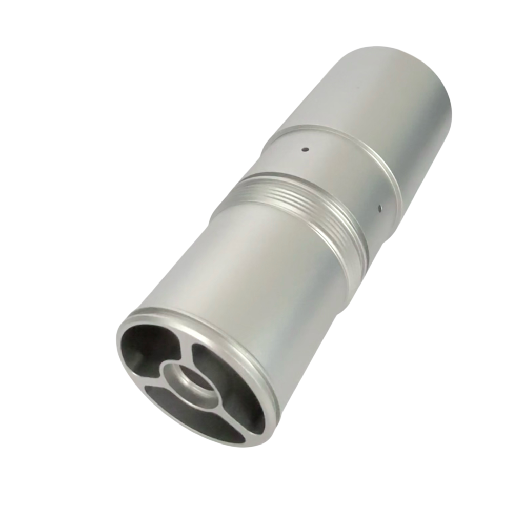
Hydraulic Component Solutions
/ HYDRAULIC SYSTEM COMPONENT SOLUTION
Hydraulic System Machined Component Solutions
FREEFLY CNC supports hydraulic-system projects through machined manifolds, valve bodies, sleeves, spools, fittings, nozzles and plates where passages, threaded ports, sealing faces and inspection sequence decide production fit.
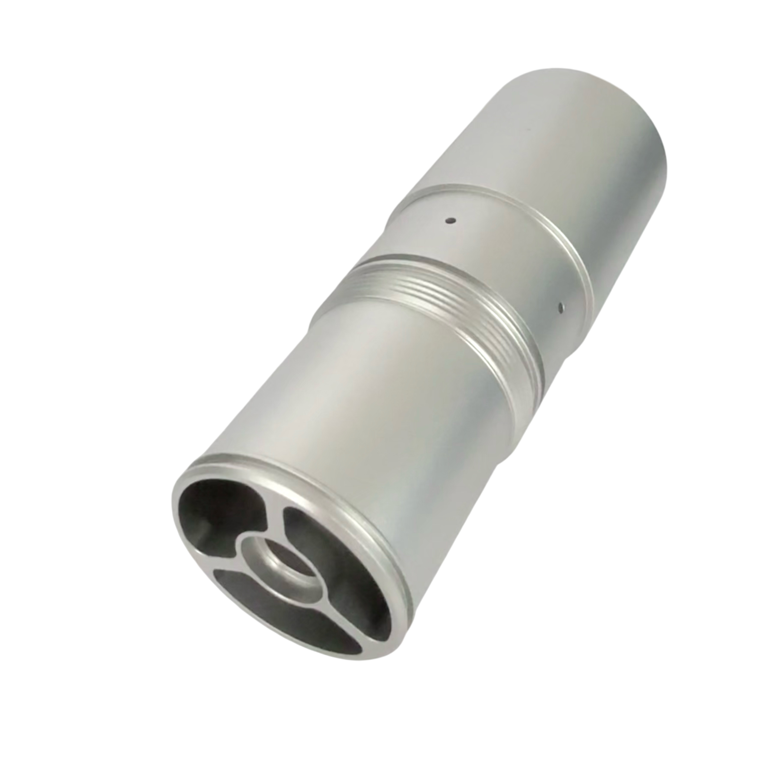
PASSAGES
Cross holes, flow paths and intersecting structures reviewed by drawing.
SEALING FACES
Flatness, contact surfaces and edge condition tied to assembly fit.
THREADED PORTS
BSP, NPT, metric, UNF or drawing-defined thread requirements.
PRODUCTION STAGE
Prototype, small batch and repeat production reviewed by route fit.
/ HYDRAULIC COMPONENTS
Hydraulic Parts Need More Than A Machined Shape
Hydraulic-related turned components are defined by passages, threaded ports, sealing surfaces and assembly-related features. A clear component requirement separates each critical feature before machining, finishing and inspection are planned.
/ COMPONENT SURFACE
Common Hydraulic Component Types
Separate the component family early so passages, threaded ports, sealing faces, roundness, flatness and assembly features can be reviewed against the right machining route.
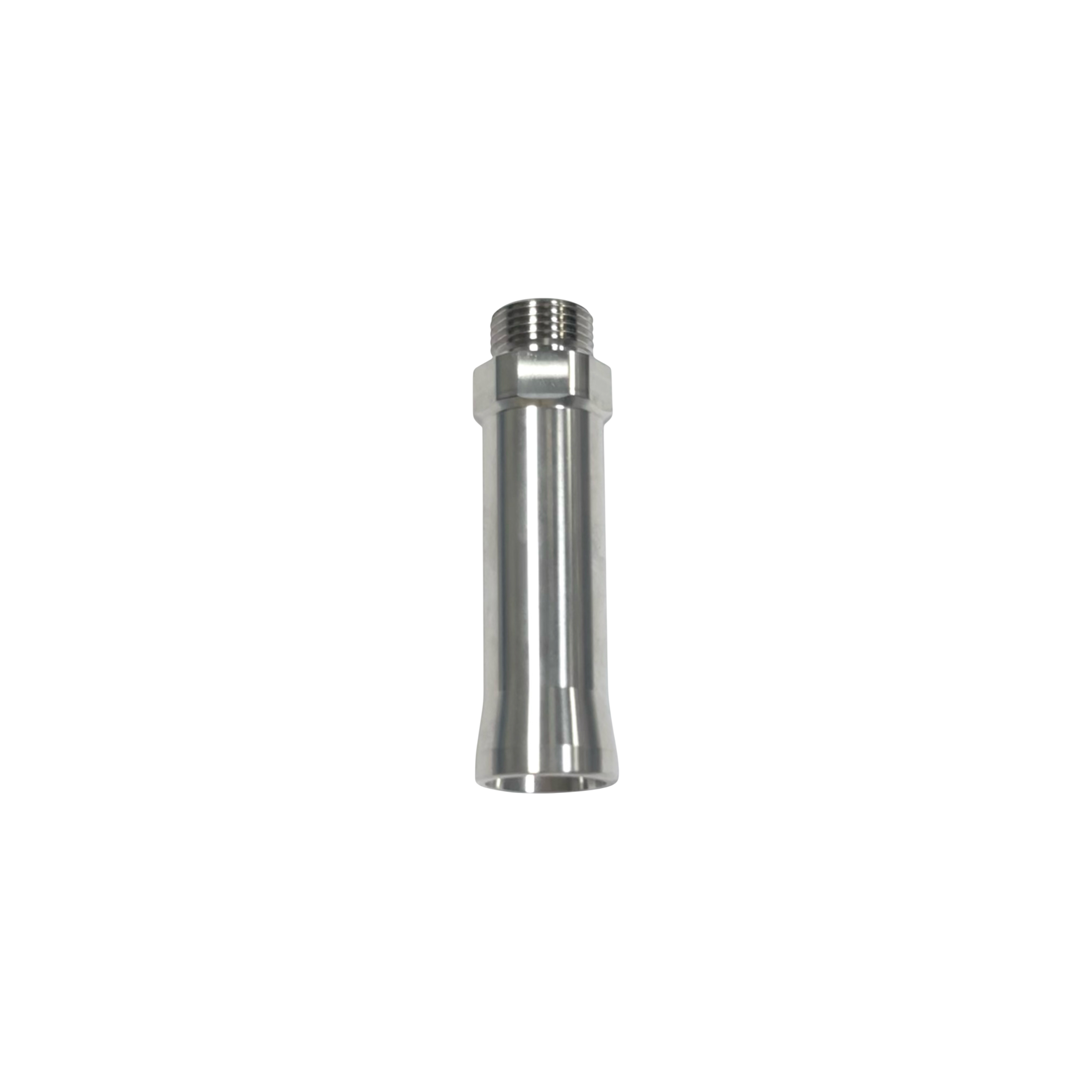
Sleeves, Spools And Pistons
Roundness, concentricity, bore fit, surface finish and usable thread depth.
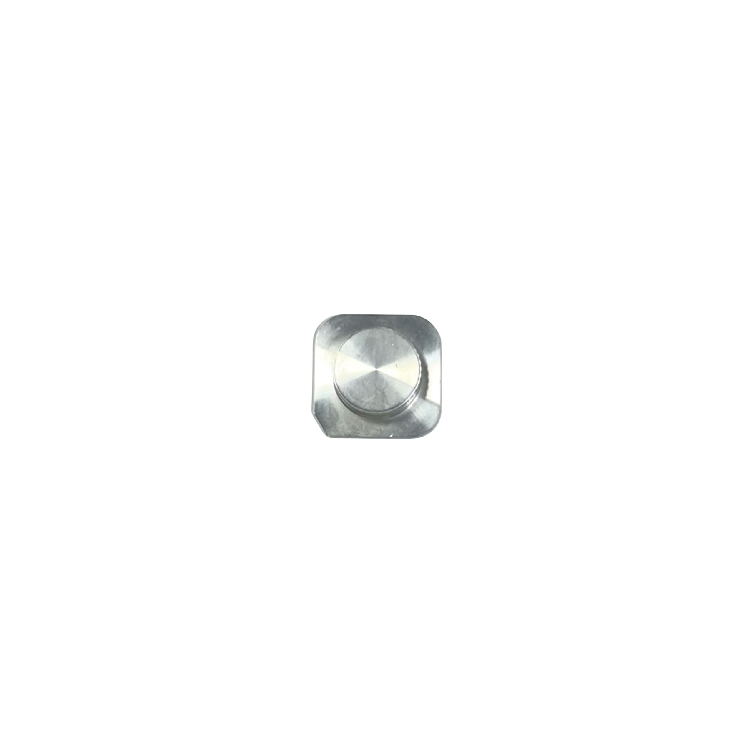
Fittings, Nozzles And Connectors
External and internal threads, wrench flats, shoulders, sealing faces and mating geometry.
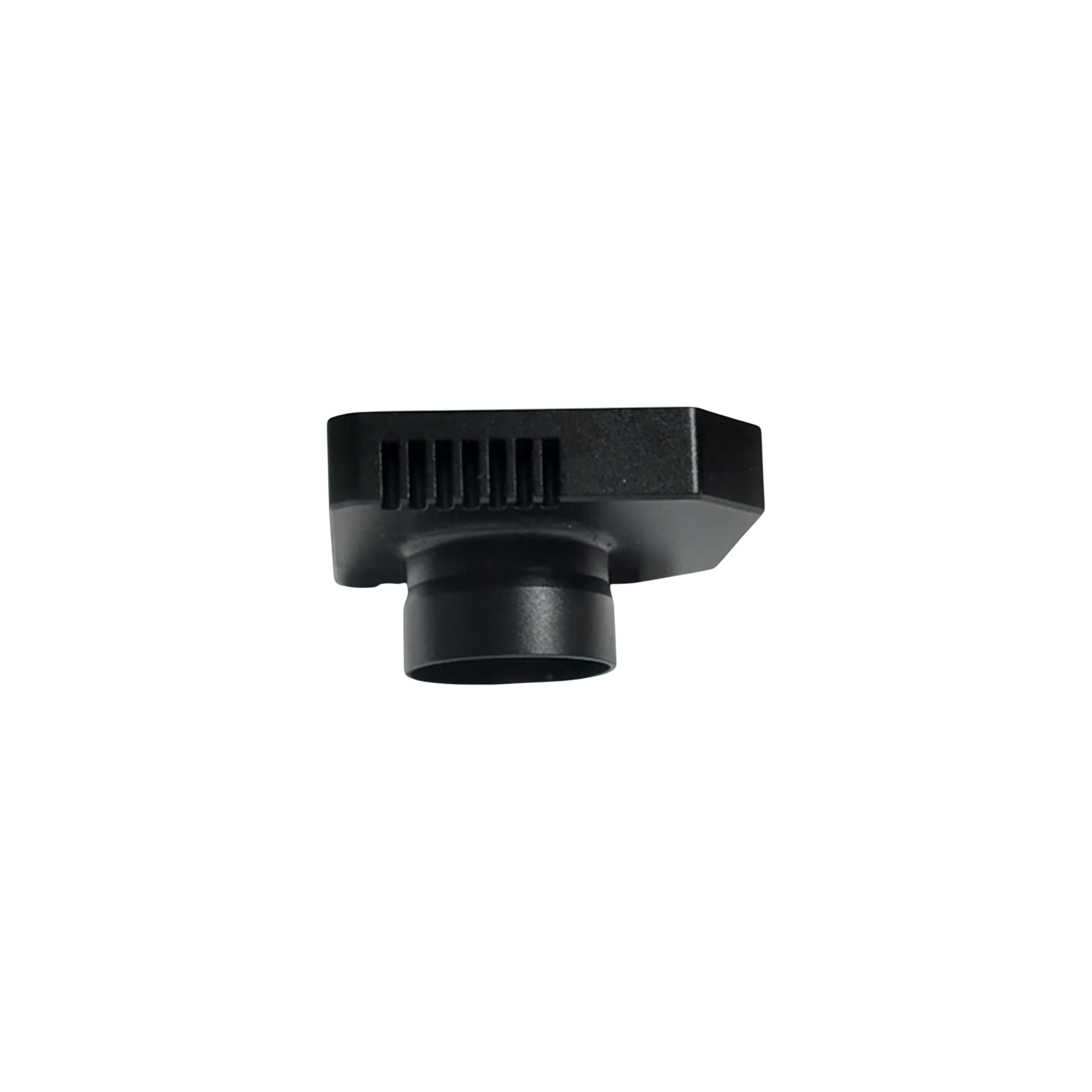
Plates And Structural Parts
Passages, orifices, thread features, bore condition and edge control.
ACTIVE VIEW
Manifold Body
Multi-face machining, cross-hole intersections, datum surfaces and threaded ports must be planned as one route.
/ SLIDE REVIEW
Hydraulic Component Families
Click each label-style control to review the product family and the engineering note. This keeps the module product-led while preserving the static draft’s scan path.
/ COMPONENT INPUTS
Hydraulic Component Details
Clear input keeps manufacturability, process sequence and inspection requirements visible before production planning.
01 / Component Type
Manifold, valve body, sleeve, spool, piston, fitting, connector, nozzle, mounting plate or adapter plate.
02 / Critical Features
Passages, intersecting holes, threaded ports, sealing faces, flatness, concentricity, burr control and matching components.
03 / Quote Inputs
CAD or 2D dimensions, material grade, finish, quantity stage, thread standard, tolerance notes and assembly context.
/ COMPONENT FAMILIES
Three Hydraulic Part Groups Need Different Review
A fitting, sleeve, nozzle or valve-related component should be reviewed by the features that control sealing, flow and assembly.
01 / MANIFOLD AND VALVE BODY MACHINING
Passages, Ports And Sealing Features
Hydraulic manifolds and valve bodies often combine multi-surface machining, internal flow paths, intersecting holes, threaded ports and sealing features. Flatness, perpendicularity, hole position and internal burr control should be reviewed before the route is confirmed.
- External profiles and datum reference surfaces
- Cross-hole and multi-directional drilling
- Threaded ports including BSP, NPT, metric and UNF when specified
- Sealing feature machining and edge condition review
02 / PRECISION TURNED COMPONENTS
Roundness, Concentricity And Fit
Shafts, spools, sleeves, pistons and fittings depend on controlled diameters, surface finish, thread quality and repeatable mating fit. These are turning-led components, but secondary features and inspection timing still need to be planned.
- Roundness, concentricity and dimensional consistency
- Internal and external surface finish requirements
- Thread quality and usable depth
- Burr control for sliding, sealing and assembly interfaces
03 / PLATES AND STRUCTURAL COMPONENTS
Passages, Orifices And Edge Control
Hydraulic plates, adapter plates and structural components are sensitive to flatness, mounting-hole accuracy, thickness consistency and deformation from clamping or multi-step machining.
- Mounting and adapter plate machining
- Profile, counterbore and threaded-hole features
- Flatness and thickness consistency
- Stable batch review where repeat production is required
/ QUALITY CONTROL
Verification Follows Hydraulic Function
Precision machining is only one part of hydraulic component production. The inspection plan should match passages, sealing features, threaded ports and assembled fit.
Hole And Thread Verification
Hydraulic passages, threaded holes, matching holes and intersecting structures are checked because deviation can affect flow, sealing and assembly.
Sealing Surface Inspection
Sealing surfaces, contact areas and edge condition are controlled because they directly influence leakage risk and assembly stability.
Dimensional Verification
Position accuracy, hole distance, concentricity and critical dimensions should be verified where the drawing makes them critical.
Assembly Verification
Sleeves, inserts, plugs and matching components need fit review so the machined part works in the final assembly.
/ MATERIALS AND FINISHES
Material And Surface Requirements Change The Route
The RFQ should state material grade, finish, hardness or corrosion expectations when they matter. Final material and finish lists should be confirmed before live quotation.
Materials
Hydraulic-related turned parts may use steel, stainless steel, brass or aluminum when suitable. Grade and documentation requirements should be shared before production planning.
- Material grade and standard
- Hardness or heat-treatment notes when required
- Compatibility with finish and assembly conditions
Surface Finishes
Surface treatment can affect sealing, corrosion resistance, appearance and thread protection. Masking and finish thickness should be reviewed where fit is critical.
- Anodizing, plating or coating requirements if specified
- Surface roughness or cosmetic expectations
- Thread, bore and sealing-face protection during finish
/ HYDRAULIC PROJECT SUPPORT
From CAD Review To Verified Components
Hydraulic work needs the drawing, process route and inspection plan to be connected before production starts.
CAD And Drawing Review
Review dimensions, material, thread standards, passages and surface requirements.
Process Route Planning
Plan milling, turning, drilling, tapping, deburr, finish and inspection sequence together.
Sealing And Fit Control
Focus on sealing faces, flatness, concentricity, bore fit and matching component relationships.
Quality Verification
Use dimensional checks, surface review and feature-specific inspection before shipment release.
Batch Support
Support sample, small-batch and repeat production where geometry and requirements fit the route.
/ ORDER PROCESS
From Hydraulic Drawing To Released Parts
A clear order path keeps hydraulic requirements connected from RFQ through engineering review, sampling, repeat production and final release.
01
Send RFQ
Share geometry, material, quantity and assembly context.
02
Engineering Review
Confirm material, process route and critical features.
03
Quotation
Review scope, quantity stage and inspection expectations.
04
Sample Review
Produce and validate sample or small-batch route where suitable.
05
Repeat Production
Move into repeat production when geometry and demand support it.
06
Inspection Release
Check dimensions, features, finish and packing before shipment release.
/ PROCESS AND INSPECTION
From Hydraulic Requirement To Released Components
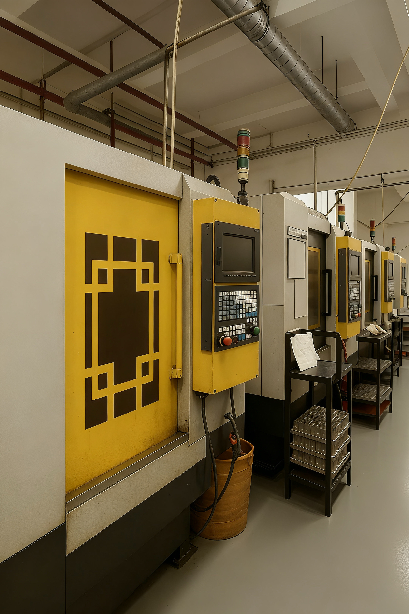
Hydraulic-related components need the drawing, process route and inspection plan connected before production starts. FREEFLY CNC reviews machining sequence, sealing features, bore fit, edge condition and release checks as one manufacturing path.
- 01 / Send drawings, material, quantity and assembly context
- 02 / Review passages, sealing faces, threads, bores and burr risks
- 03 / Plan turning, milling, drilling, tapping, deburr, finish and inspection sequence
- 04 / Validate sample or small-batch route where geometry and material are suitable
- 05 / Release repeat production with feature-specific inspection and packing checks
/ HYDRAULIC SOLUTION FAQ
Questions Before Sending A Hydraulic Drawing
These notes apply when the requirement is for a machined hydraulic-related component rather than a complete hydraulic assembly.
What hydraulic components can FREEFLY CNC support?
Hydraulic-related manifolds, valve bodies, spools, sleeves, pistons, fittings, connectors, nozzles, mounting plates and adapter plates can be reviewed when the drawing and process route fit the capability.
Is this a complete hydraulic system supply page?
No. The page is positioned for machined components used in hydraulic systems. Final system design, pump assembly, hose assembly and complete hydraulic-system integration are outside the stated scope unless separately verified.
Which features need the most attention?
Passages, cross holes, threaded ports, sealing faces, mounting faces, flatness, concentricity, burr control and matching component relationships should be marked clearly.
What should I include in the RFQ?
Send CAD or 2D drawings, material grade, finish requirements, quantity stage, thread standards, tolerance notes, critical features and any assembly context that affects sealing or fit.
Can prototype and repeat production both be reviewed?
Yes, where geometry, material and route fit the capability. Use prototype, small batch and repeat production language rather than unsupported mass-production promises.
/ START WITH THE DRAWING
Send The Part. We Will Review The Route.
Share the drawing, material, quantity, tolerance notes, finish and secondary-operation requirements. FREEFLY CNC reviews the component as a finished production part, not a single isolated operation.
RFQ Inputs That Help Engineering Review
- 2D or 3D drawings with critical features marked
- Material grade, finish, thread standard and quantity stage
- Assembly context when sealing, fit or matching parts matter
- Inspection expectations and any CTQ notes
Drawing Review
Geometry, material, thread standards and sealing features reviewed together.
Manufacturing Route
Turning, milling, drilling, tapping, deburr, finish and inspection planned as one route.
Release Checks
Dimensions, surfaces, threads, finish and packing checked before shipment.